3. Isometric Projection
To obtain an isometric
projection, we simply need to set the orthographic projection up as
described and then rotate the camera so that it looks upon the scene
from an angle, instead of straight on.
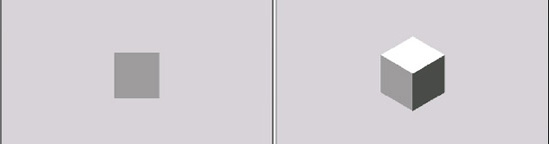
The effects of this camera rotation can be seen in Figure 4.
The two images both display a unit-size cube with an orthographic
projection. On the left, the camera is looking directly along the
negative z axis, so only the front face of the cube can be seen. On the
right, the camera has been moved so that it looks from the point (1, 1,
1) toward the origin point (0, 0, 0). As a result, the cube is now seen
with its corner facing toward the camera. Note that the cube's front
face (lit in medium gray) is now appearing at the bottom left of the
cube; this should help you to visualize how the camera position has
moved.
The code required to set the camera into this position is shown in Listing 2. This replaces the previous calculation of the view matrix in the game's Initialize function.
Example 2. Setting the camera position for an isometric projection
// Calculate a view matrix (where we are looking from and to) for isometric projection
      Matrix view = Matrix.CreateLookAt(new Vector3(1, 1, 1), Vector3.Zero, Vector3.Up);
|
With the camera so
positioned, the world axes are shifted so that they are no longer
aligned with the screen axis. Moving an object along the positive x axis
will now cause it to move to the right and down on the screen. Moving
an object along the positive z axis will cause it to move left and down
on the screen, and the positive y axis will move up on the screen.
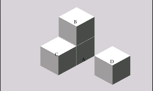
These positional effects can be seen in Figure 5.
The cube labeled A is at position (0, 0, 0), the cube labeled B is at
position (0, 1, 0), the cube labeled C is at position (0, 0, 1), and the
cube labeled D is at position (2, 0, 0).
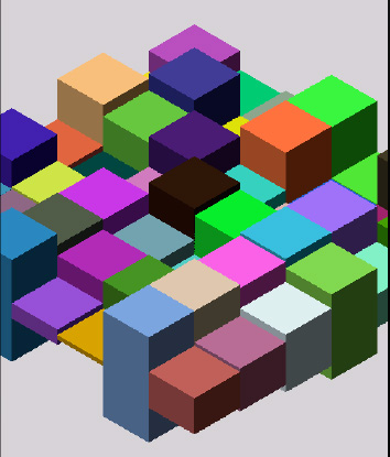
An example of using an isometric projection can be seen in the Isometric
project accompanying this chapter. It sets up a grid of unit-size cubes
along the x and z planes, and then scales them along the y axis to make
them increase and decrease in height. An image from the project can be
seen in Figure 6.
Using an isometric view
of an orthographic projection will be useful in only a minority of
games, but for those that do need it, XNA's rich 3D features create a
powerful environment for displaying such graphical environments.
4. Pixel-Aligned Projection
We can also use orthographic
projections to align the coordinate system exactly to the pixels on the
screen. This is generally useful only for 2D rendering, and in many
cases will be more easily achieved by simply using XNA's sprite
technology instead. As you have seen by now, however, there are features
that the 3D rendering environment offers that sprites cannot achieve,
such as powerful matrix-based positioning and flexible lighting.
To set up a pixel-aligned
projection, we simply need to provide the actual viewport width and
height when creating the matrix, as shown in Listing 3.
Given a width of 480 and a height of 800, this configuration will
create a coordinate system ranging from position (−240, −400) in the
screen's bottom-left corner to position (240, 400) in its top-right
corner.
Example 3. Creating a pixel-aligned orthographic projection matrix
// Create a pixel-aligned orthographic projection
        Matrix projection = Matrix.CreateOrthographic(GraphicsDevice.Viewport.Width,
                                                GraphicsDevice.Viewport.Height, 0, 100);
|
This works fine, but has put
the origin (0, 0) coordinate in the center of the screen. Normally when
working with 2D coordinate systems (such as the one used by XNA's
sprites), the origin is in the top-left corner, and the positive y axis
points toward the bottom of the screen. We can replicate this same
system by using a different projection matrix creation function: CreateOrthographicOffCenter.
This function expects six parameters to be passed, as follows and in this order:
left: the coordinate to use to represent the left edge of the screen
right: the coordinate for the right edge of the screen
bottom: the coordinate for the bottom edge of the screen
top: the coordinate for the top edge of the screen
zNearPlane: the near clipping plane distance
zFarPlane: the far clipping plane distance
Any values can be passed for the left, right, bottom, and top
coordinates, so we can set the left and top values to be zero, and the
right and bottom to be the viewport width and height, respectively. Listing 4 shows an example of setting the projection up in this way.
Example 4. Creating an off-center pixel-aligned orthographic projection matrix
// Create a pixel-aligned orthographic projection with its origin in the top-left
        // of the screen.
        Matrix projection = Matrix.CreateOrthographicOffCenter
                                                (0, GraphicsDevice.Viewport.Width,
                                                 GraphicsDevice.Viewport.Height, 0,
                                                 −100, 100);
|
If you wanted to put the origin (0, 0) coordinate to the bottom left instead, simply swap the bottom and top parameters and the whole display will flip vertically to achieve this.